Search This Blog

Showing posts with label Arduino. Show all posts

Wednesday, September 19, 2018

Safe and easy DIY Home Energy Monitor Using Current Transformer with Arduino, Raspberry Pi, or Beaglebone Black

အိမ်မှာ ရှိတဲ့ လျှပ်စစ် အသုံး အဆောင် တွေရဲ့ စွမ်းအင် အသုံး ပြုမှု ကို စီစစ် တိုင်းတာ ဖို့ အတွက် ရိုးရှင်း ပြီး၊ အခြေခံ ကျတဲ့ energy monitor တစ်ခု ကို လုပ်ကြည့် ပါမယ်။ တိုင်းတာ အသုံး ပြုတဲ့ နည်း အများကြီး ရှိပေ မယ့် သင်ယူ လေ့လာမှု အတွက် အထောက် အကူ ဖြစ်ဖို့ ရော၊ အန္တရာယ် ကင်းဖို့ အတွက်ပါ သင့်တော်မှု ရှိမယ် ထင်တဲ့ YHDC Current Transformer SCT-013-000 [YHD18] ကို သုံးဖို့ ရွေးချယ် လိုက်ပါ တယ်။ သူက split-core ဖြစ်ပြီး တိုင်းတာ ချင်တဲ့ ဗို့အား မြင့် ဝါယာ လိုင်း တွေကို ဘာမှ ဖြုတ် စရာ မလိုပဲ ဝါယာ ပေါ်ကို ပတ်ပြီး ကလစ် တပ်လိုက် ဖို့ပဲ လိုတာမို့ non-invasive ဖြစ်ပြီး၊ အန္တရာယ် လည်းကင်း၊ အသုံးပြုဖို့လည်း လွယ်ကူ ပါတယ်။ အဲဒီ လို ပတ်တဲ့ အခါ Figure 1 ရဲ့ ညာဖက် ဆုံးမှာ ပြထား သလို ဝါယာ တစ်စ ကိုပဲ ပတ်ရ မှာဖြစ် ပါတယ်။


Figure 1. (ဘယ်ဘက်) SCT-013 က split core ဖြစ်တဲ့ အတွက် ကလစ်ကို ဖွင့်ပြီး ဝါယာ ပေါ်ကို အလွယ် တကူ တပ်ဆင်နိုင် ပါတယ်။ (အလယ်) ဝါယာ အကုန်လုံးကို ပတ်လိုက်ရင် အဝင် နဲ့ အထွက် ပြန်ကြေပြီး core ထဲမှာ ဖြတ်စီး တဲ့ စုစုပေါင်း current က သုည ဖြစ်သွား တဲ့ အတွက် တိုင်းလို့ မရ ပါဘူး။ (ညာဖက်) ဝါယာ တစ်စ ကို ပဲ core ထဲမှာ ပတ်ဖို့ လိုပါတယ်။


Friday, August 10, 2018

DIY Programmable Function Generator Using Arduino Uno

Arduino Uno ကို function generator အနေ နဲ့ သုံးပြီး လိုချင် တဲ့ low frequency waveform တွေကို စိတ်ကြိုက် ထုတ်နိုင် ပါတယ်။ သူ့ရဲ့ အားသာချက် က လိုသလို ပရိုဂရမ် ရေးပြီး စိတ်ကြိုက် customize အမျိုးမျိုး ထုတ်နိုင်၊ အချိန် အလိုက် ပြောင်းနိုင် တာဖြစ်ပြီး၊ အားနည်း ချက်ကတော့ အရမ်း မြင့်တဲ့ frequency တွေကို ထုတ် မပေးနိုင် တာ ဖြစ်ပါတယ်။ Arduino ရဲ့ analog output က pwm သုံးထား တာမို့ ရလဒ် ပိုကောင်းအောင်၊ pwm frequency ကို 8 kHz လောက် ပြောင်းထား ပါတယ်။ ဒီထက် ရလဒ် ပိုကောင်း ချင်ရင် DAC နဲ့ တွဲသုံး လို့လည်း ရပါတယ်။


Figure. Arduino function generator ၏ အထွက်ကို oscilloscope ဖြင့် တိုင်းတာ ရရှိပုံ။


Monday, May 14, 2018

MCP3008 - Analog to Digital Converter with SPI Interface

MCP3008 က Microchip က ထုတ်တဲ့ 8-channel, 10-bit analog to digital converter ဖြစ်ပါတယ်။


Figure. MCP3008 ၏ pin များ။


သူ့ကို single ended analog input အနေနဲ့ ရှစ်ခု သုံးလို့ ရပြီး၊ differential input pair အနေနဲ့ ဆို လေးစုံ သုံးလို့ ရပါတယ်။ Power supply ဗို့ 2.7 V ကနေ 5 V အထိ သုံးလို့ ရပြီး၊ အပူချိန် -40 °C ကနေ +85 °C အထိ ခံနိုင် ပါတယ်။ SPI interface ဖြစ်ပြီး mode 0 ဒါမှ မဟုတ် mode 3 နဲ့ သုံးနိုင် ပါတယ်။

Wednesday, September 13, 2017

Pixy

Arduino, Raspberry Pi, BeagleBone စတာ တွေနဲ့ Computer Vision အလွယ်တကူ တွဲသုံး ချင်ရင် Pixy (http://cmucam.org/projects/cmucam5) ဆိုတဲ့ Vision System လေး သုံးရတာ လွယ်ကူ အဆင်ပြေ ပါတယ်။ ကိုယ် detect လုပ်ချင် တဲ့ အရာ ဝတ္တု တွေရဲ့ အရောင် ကို သင်ပေး ပြီးတာနဲ့ သူတို့ ကို အာရုံခံ ပေးပြီး နေရာ၊ အရွယ် စတာ တွေကို UART, SPI, I2C အစရှိတဲ့ interface တွေ နေ ပို့ ပေးနိုင် ပါတယ်။

Wednesday, August 10, 2016

TFT LCD Touch Screen - ILI9341

Aliexpress ကနေ 2.4 inch 240 x 320 resolution ရှိတဲ့ TFT LCD touch screen လေး ဝယ်ပြီး သုံးကြည့်ဖြစ်ပါတယ်။


အဲဒီ module လေးက LCD display ရော၊ touch input ရော၊ SD card reader လေးပါ ပါပါတယ်။ Adafruit libraries တွေကို သုံးပြီး ကျွန်တော် ရေးကြည့်ထားတဲ့ နမူနာ program တချို့ကို

https://github.com/yan9a/TFT_LCD_Touch_Arduino

မှာ တွေ့နိုင်ပါတယ်။

Thursday, July 7, 2016

Motor Driver - DRV8834

Stepper motor AM1020-V-6-65 လေးကို drive လုပ်ဖို့ အတွက် motor driver လေးတခု design လုပ်ဖြစ်ပါတယ်။ အစက Allegro ရဲ့ A4988 ကို သုံးဖို့ စဉ်းစားပေမယ့် motor အတွက် supply voltage က 8V - 35V ဖြစ်နေတော့ လက်ရှိ 6V motor နဲ့ မကိုက်တာ တကြောင်း၊ chip အရွယ်ကလည်း 5 mm x 5 mm ဖြစ်နေတော့ ကိုယ်လိုချင်တဲ့ အရွယ်ထက် နည်းနည်း ကြီးနေတာတကြောင်းကြောင့် တခြား driver ကို ထပ်ရှာဖြစ်ပါတယ်။ TI ရဲ့ DRV8835 ကျပြန်တော့ 2 mm x 3 mm အရွယ်လေးကို သဘောကျပေမယ့် DC motor တွေအတွက်အဓိက ရည်ရွယ်ထားတာမို့ stepper motor ကို အလွယ်တကူ ထိန်းဖို့ indexer မပါတာကို တွေ့ရပါတယ်။ ဒါနဲ့ 4 mm x 4 mm အရွယ်၊ motor supply voltage 2.5V - 10.8V ရပြီး၊ 1.5A per coil ရတဲ့ DRV8834 ကိုပဲ ရွေးလိုက်ပါတယ်။

Wednesday, May 18, 2016

DS1307 Real-time Clock

DS1307 Real-time clock လေးကို အသုံးပြုပုံ အကြောင်း ပြောချင်ပါတယ်။ AliExpress က module လေးဝယ်တာ ၁ ဒေါ်လာလောက်ပဲ ပေးရပါတယ်။ AT24C32 ဆိုတဲ့ 32k EEPROM လေးပါ အဆစ် ပါသေးတယ်။


Figure. Setup.


Sunday, April 17, 2016

Adaptive Filter: BMFLC

Adaptive noise canceling techniques တွေဖြစ်တဲ့
  1. Fourier Linear Combiner (FLC)
  2. Weighted-frequency Fourier Linear Combiner (WFLC)
  3. Bandlimited Multiple Fourier Linear Combiner (BMFLC)

အစရှိတဲ့ filter တွေ အကြောင်း ပြောချင်ပါတယ်။ FLC က frequency သိတဲ့ periodic signal တခုရဲ့ amplitude နဲ့ phase ကို least mean square (LMS) algorithm သုံးပြီး adapt လုပ်ယူ ခန့်မှန်းတာပါ။ WFLC ကတော့ FLC ကို ထပ်မံဖြည့်စွက်ပြီး frequency ကိုပါ သိစရာ မလိုပါဘူး။ ဒါကြောင့် FLC လို frequency အသေဖြစ်စရာ မလိုပဲ၊ frequency ပြောင်းလဲနေ တဲ့ reference signal တွေကို ပါ adapt လုပ်နိုင်ပါတယ်။ WFLC ရဲ့ အားနည်းချက်က reference signal မှာ dominant frequency တွေ အများကြီး ပါနေရင် အလုပ်ကောင်းကောင်း မလုပ်နိုင်တော့ ပါဘူး။ အဲ့ဒါကို ဖြေရှင်းဖို့ အတွက် ကြိုတင်သတ်မှတ်ထားတဲ့ frequency band ထဲက dominant frequency တွေ အများကြီးကို track လုပ်နိုင်တဲ့ BMFLC ကို သုံးနိုင်ပါတယ်။


Setup

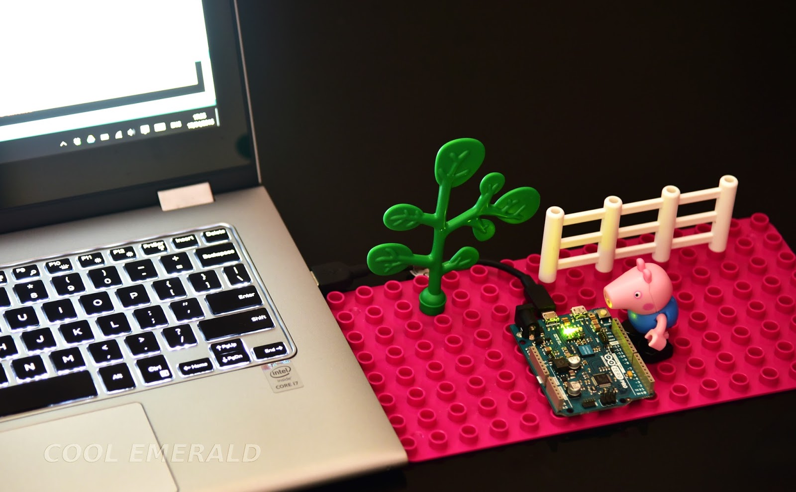
Arduino zero pro ကို သုံးပြီး စမ်းကြည့်ပါမယ်။ Code တွေကို အခြား platform ပေါ်တွေမှာ ပါ အလွယ် တကူ ယူသုံးနိုင်အောင် C နဲ့ပဲ ရေးလိုက်ပါတယ်။ ပထမ အနေနဲ့ reference signal ကို generate လုပ်ကြည့်ပြီး noise ပေါင်းထည့်ပါမယ်။ အဲဒီ signal ကိုပဲ adaptive filter နဲ့ စစ်ပြီးတဲ့အခါ serial plotter မှာ မူရင်း reference signal နဲ့ နှိုင်းယှဉ် plot လုပ်ကြည့်ပါမယ်။ အခုနောက်ပိုင်း Arduino IDE တွေမှာ Serial Monitor နဲ့ အတူ၊ Serial Plotter ပါပါလာတော့ အဝင် signal ပြောင်းသွားတဲ့အခါ adaptive filter က ဘယ်လို adaptive လုပ်သွားတယ် ဆိုတာ serial plotter မှာ ကြည့်ရတာ ပိုပြီး ထင်သာမြင်သာ ရှိပါတယ်။


Figure. A simple setup using an Arduino Zero Pro board.


Thursday, March 24, 2016

Gyroscope L3G4200D

L3G4200D ဆိုတဲ့ STMicroelectronics ကထုတ်တဲ့ MEMS ultra-stable three-axis digital output gyroscope ကို သုံးကြည့်ဖြစ်ပါတယ်။ Aliexpress မှာ ရောင်းတဲ့ L3G4200D Module လေးက ၃ ဒေါ်လာ လောက်ပဲ ပေးရပါတယ်။


Figure. L3G4200 Gyroscope module


Tuesday, November 17, 2015

Driving 28BYJ-48-5V Stepper Motor with ULN2003A Transistor Arrays on Arduino

28BYJ-48-5V Stepper Motor နဲ့ ULN2003A driver တွေက တော်တော် အသုံးများပုံရပြီး အလွယ်တကူ ဝယ်နိုင်ရုံတင်မက စျေးလည်း တော်တော်ပေါ ပါတယ်။ Stepper Library ကို မသုံးပဲ Arduino ရဲ့ Port B ကို သုံးပြီး Stepper motor ကို ထိန်းတဲ့ ရိုးရှင်းတဲ့ နမူနာလေး ဖော်ပြချင်ပါတယ်။


Figure. Driving 28BYJ-48-5V Stepper Motor with Arduino UNO using USB power.


28BYJ-48-5V Stepper Motor က 5V နဲ့ တိုက်ရိုက်မောင်းနိုင်ပြီး၊ unipolar stepper motor အမျိုးအစားပါ။ သူ့ရဲ့ schematic ကို အောက်မှာပြထားပါတယ်။


Figure. 28BYJ-48-5V Stepper Motor.


ULN2003A Transistor Arrays ကတော့ inductive load တွေကို drive လုပ်ဖို့ ဒီဇိုင်းလုပ်ထားတာမို့ အထဲမှာ free wheeling diode ပါ ပါ ပါတယ်။ Darlington pair သုံးထားတာမို့ အဝင် ဗို့ 1.4V လောက်ကနေ 30V အထိ ကြိုက်တဲ့ ဗို့နဲ့ တိုက်ရိုက်ဆက်ပြီး ထိန်းနိုင်ပါတယ်။


Figure. ULN2003A.


Wave drive, Full step drive နဲ့ Half step drive တွေကို သုံးပြထားတဲ့ နမူနာ ပရိုဂရမ် လေးကို အောက်မှာ ပြထားပါတယ်။


//Driving 28BYJ-48-5V Stepper Motor using ULN2003A Transistor Arrays
//Author: Yan Naing Aye
//Website: http://www.cool-emerald.com/

#include "StepperPortB.h"
//----------------------------------------------------------
void setup() {    
  StepperInit();//setup pins
  //StepperMode(WAVE);
  //StepperMode(FULL);
  StepperMode(HALF);
  //Serial.begin(9600);
}
void loop() {
  Step(4096,2500); //turn 4096 steps forward with 2500 us period for each step
  Step(-4096,2500);//turn 4096 steps backward with 2500 us period for each step
  //Serial.println(CS);
}


//File: StepperPortB.h
//Author: Yan Naing Aye
//Website: http://www.cool-emerald.com/

//Driving 28BYJ-48 – 5V Stepper Motor using ULN2003A Transistor Arrays
//----------------------------------------------------------
#ifndef StepperPortB_h
  #define StepperPortB_h
  #include "Arduino.h"
byte* S; //Stepping sequence

//Wave drive
//Step          0 | 1 | 2 | 3 | 0 |...

//Blue   = A :  1 | 0 | 0 | 0 | 1 | ...
//Pink   = B :  0 | 1 | 0 | 0 | 0 | ...
//Yellow = C :  0 | 0 | 1 | 0 | 0 | ...
//Orange = D :  0 | 0 | 0 | 1 | 0 | ...
byte Wave[4] = {0x01,0x02,0x04,0x08};

//Full Step drive
//Step          0 | 1 | 2 | 3 | 0 |...

//Blue   = A :  1 | 1 | 0 | 0 | 1 | ...
//Pink   = B :  0 | 1 | 1 | 0 | 0 | ...
//Yellow = C :  0 | 0 | 1 | 1 | 0 | ...
//Orange = D :  1 | 0 | 0 | 1 | 1 | ...  
byte FullStep[4] = {0x09,0x03,0x06,0x0C};

//Half Step drive
//Step          0 | 1 | 2 | 3 | 4 | 5 | 6 | 7 | 0 |...

//Blue   = A :  1 | 1 | 1 | 0 | 0 | 0 | 0 | 0 | 1 |...
//Pink   = B :  0 | 0 | 1 | 1 | 1 | 0 | 0 | 0 | 0 |...
//Yellow = C :  0 | 0 | 0 | 0 | 1 | 1 | 1 | 0 | 0 |...
//Orange = D :  1 | 0 | 0 | 0 | 0 | 0 | 1 | 1 | 1 |...
byte HalfStep[8] = {0x09,0x01,0x03,0x02,0x06,0x04,0x0C,0x08};
int CS=0;//Current step
int N;
//----------------------------------------------------------
//Mode definition
#define HALF 0
#define FULL 1
#define WAVE 2
//Define the mode to drive the stepper motor
void StepperMode(int Mode) {  
  if(Mode==WAVE) {S=Wave; N=4;}
  else if(Mode==FULL) {S=FullStep; N=4;}
  else {S=HalfStep; N=8;}
}
//----------------------------------------------------------
//Turn stepper motor n steps
//with t microseconds period for each step
//positive n for forward dir and negative n for backward dir
void Step(int n,int t) {
  int CD=1; 
  if(n<0) {n*=-1; CD=-1;}
  for(int i=0;i<n;i++) {
    CS=(CS+(N+CD))%N;
    PORTB=S[CS];
    delayMicroseconds(t);
  }
}
//----------------------------------------------------------
//Initialize
void StepperInit() {
  //Setup port B (digital pin 8 to 13)
  //The two high bits (6 & 7) map to the crystal pins and are not usable
  //only 4 pins - 8 to 11 are used in this program
  //where Blue - pin 8 (LSB), Pink -pin 9, Yellow -pin 10, Orange -pin 11
  DDRB=0xff;
  PORTB = 0x00;  
}
//----------------------------------------------------------
#endif

Friday, September 25, 2015

Adafruit CC3000 WiFi for Arduino

WiFi သုံးပြီး microcontroller နဲ့ ဆက်သွယ်တဲ့ ဟာကို Arduino Uno နဲ့ Adafruit CC3000 WiFi Shield ကိုသုံးပြီး စမ်းကြည့်ထားတာပါ။ သူက Arduino ရဲ့ standard WiFi shield မဟုတ်တဲ့ အတွက် WiFi.h library ကို သုံးလို့မရပါဘူး။ ဒါ့ကြောင့် Adafruit CC3000 library ကို ဒေါင်းလုပ်လုပ်၊ un-zip လုပ်ပြီး C:\Program Files (x86)\Arduino\libraries folder ထဲမှာ ထည့်ဖို့လိုပါတယ်။


Figure. Adafruit CC3000 WiFi shield stacked with Arduino Uno.


Saturday, September 19, 2015

Controlling Your Hardware from the Web Using Arduino

Arduino Ethernet shield 2 ကိုသုံးပြီး အင်တာနက်ကနေ သင့်ရဲ့ hardware တွေကို လှမ်းပြီး ထိန်းတဲ့အကြောင်း ဆွေးနွေးချင်ပါတယ်။ Arduino Ethernet 2 Library ကိုသုံးပြီး server အနေနဲ့ နမူနာတခု၊ client အနေနဲ့ တမျိုး စမ်းကြည့်ပါမယ်။ နောက်ဆုံး version Arduino IDE ကို သုံးဖို့လိုပါတယ်။ ဒီနမူနာမှာတော့ Arduino IDE 1.7.6 ကိုသုံးထားပါတယ်။ Arduino Uno ကို Ethernet shield 2 တပ်ထားတဲ့ပုံကို အောက်မှာ ပြထားပါတယ်။


Figure. Arduino Uno paired with Arduino Ethernet shield 2.


Thursday, September 10, 2015

Accelerometer LIS3DSH

LIS3DSH က STMicroelectronics ထုတ်တဲ့ 3-axis MEMS accelerometer တခု ဖြစ်ပါတယ်။ Full scale ကို &pm;2g ကနေ &pm;16g ထိ အမျိုးမျိုးရွေးလို့ ရပါတယ်။ အရွယ်အစားက လည်း 3mm x 3mm ပဲမို့ သေးသေးလေးပါ။ Digital output ကို SPI ဒါမှမဟုတ် I2C ကြိုက်တာသုံးလို့ရပါတယ်။ Supply voltage က 1.71 V ကနေ 3.6 V ထိပေးလို့ ရပါတယ်။ STEVAL-MKI134V1 adapter board လေး တခုဝယ်ပြီး စမ်းကြည့်ထားတဲ့ အတွေ့အကြုံ လေးအကြောင်း ပြောချင်ပါတယ်။


Figure. STEVAL-MKI134V1 - LIS3DSH adapter board for standard DIL24 socket.

Tuesday, August 4, 2015

Bluetooth Module to be Used with Microcontroller

HC-05 Master/Slave Bluetooth Module လေးက စျေးသက်သာပြီး (~SGD 16) သံုးရလွယ်တဲ့ Bluetooth module တစ်ခုဖြစ်ပြီး UART interface သံုးပါတယ်။ အဲဒီ HC-05 နဲ့ Arduino Uno microcontroller ကိုသံုးပြီး LED မီးလံုးကို ဖုန်းနဲ့ Bluetooth communication သံုးပြီး အဖွင့်၊ အပိတ် ထိန်း တဲ့ နမူနာတစ်ခု ကို ဆွေးနွေးပါမယ်။ တကယ်တော့ UART interface ပါတဲ့ ဘယ် မိုက်ကရိုကွန်ထရိုလာ မဆို သံုးလို့ရပါတယ်။


Figure. HC-05 Bluetooth module with Arduino Uno.

Thursday, March 6, 2014

Reading Rotary Encoder Using Microcontroller

Rotary encoder တွေကို ထောင့်ဘယ်လောက်လှည့်သွားသလဲ (angular position) နဲ့ ဘယ်လောက်ဘီးလည်ပြီး ရွေ့သွားလဲ (motion sensing) ဆိုတာတွေကို တိုင်းတာဖို့ သုံးလေ့ရှိပါတယ်။ Optical rotary encoder တွေမှာ အပေါက်လေးတွေ ပုံဖော်ပြီး ဖောက်ထားတဲ့ အချပ်ကလေး ပါလေ့ရှိပြီး၊ အလင်းထုတ်ပေးတဲ့ LED နဲ့ အလင်းကို အာရုံခံနိုင်တဲ့ photo detector ကြားမှာ အဲဒီ အဝိုင်းလေး လည်တဲ့အခါ၊ အလင်းကျသွား၊ အလင်းကွယ်သွားတဲ့ ပေါ်မူတည်ပြီး ဗို့အား အနိမ့်အမြင့် digital waveform တွေထွက်လာပါတယ်။


VEX Robotics Design System ကထုတ်လုပ်တဲ့ optical encoder တခု

Encoder တွေမှာ glitch တွေ မဖြစ်အောင် ပုံမှန် binary code အစား Gray code ကို သုံးလေ့ပါတယ်။ Gray code မှာ ကပ်ရပ်နံပါတ် တစ်ခုနဲ့ တစ်ခု အကြား ပြောင်းလဲတဲ့ bit အရေအတွက်က တစ်ခု ထက် မပိုတဲ့အတွက် glitch တွေ ဖြစ်မယ့် ပြဿနာကနေ ကာကွယ်ပေးပါတယ်။ Gray code 0 ကနေ 3 အထိကို အောက်က ဇယားမှာ ပြထားပါတယ်။