
Figure. L3G4200 Gyroscope module
အဲ့ဒီ module (အသေးစိတ်ကြည့်ရန်) မှာ pull up resistors တွေ၊ 3.3V ပြောင်းပေးတဲ့ QT33 LDO regulator တွေ တခါထဲ ပါတဲ့ အတွက် သူ့ရဲ့ Vcc ကို 5V နဲ့ ဆက်လည်း ပြဿနာ မရှိပါဘူး။ Arduino Uno က 5V သုံးတာမို့ အဲဒီ module ကို အောက်မှာ ပြထားတဲ့ schematic အတိုင်း ဆက်လိုက်ပါတယ်။

Figure. Schematic for connecting Arduino Uno and L3G4200.

Figure. Breadboard view for connecting L3G4200 module to Arduino Uno.
နောက်ပိုင်း Arduino IDE တွေမှာ serial plotter ပါလာတဲ့ အတွက် Gyroscope ကဖတ်လို့ ရတဲ့ တန်ဖိုးတွေကို serial plotter မှာ တခါတည်း plot လုပ်ပေးတဲ့ program for Arduino on GitHub လေးကို အောက်မှာ ပြထားပါတယ်။
#include <SPI.h>
const int CS_Pin = 10;// set pin 10 as the chip select
//SPI pin configuration: pin 11 as MOSI (SDI), pin 12 as MISO (SDO) , pin 13 as clock (SPC)

int x,y,z;
float K=8.75; // 8.75 mdps per digit for +/-250dps full scale using 16 bit digital output

void setup() {
  Serial.begin(115200);
  pinMode (CS_Pin, OUTPUT);  //Chip Select pin to control SPI
  digitalWrite(CS_Pin, HIGH);//Disable SPI
  SPI.begin();
  SPI.setBitOrder(MSBFIRST);
  SPI.setDataMode(SPI_MODE3);

  //b7 = set (1) for reading
  //b6 = cleared (0) not to auto increase address
  //b5-b0 = register address

  //digitalWrite(CS_Pin, LOW);//Enable SPI
  //-------------------------------------------------------------------------
  //SPI.transfer(0x8F);//Read 'Who am I?' register
  //x=SPI.transfer(0x00);//Get return value of Who am I
  //-------------------------------------------------------------------------
  //digitalWrite(CS_Pin, HIGH);//Disable SPI

  digitalWrite(CS_Pin, LOW);//Enable SPI
  //-------------------------------------------------------------------------
  //CTRL_REG2 = |0 |0 |HPM1|HPM0|HPCF3|HPCF2|HPCF1|HPCF0|
  //Default =   |0 |0 |0   |0   |0    |0    |0    |0    |
  //HPM = 00 => Normal (High Pass filter Mode selection)
  //HPC = 1001 => 0.1 High Pass Filter Cut-off freq configuration
  SPI.transfer(0x21);//address
  SPI.transfer(0x09);//register value to write
  //-------------------------------------------------------------------------
  digitalWrite(CS_Pin, HIGH);//Disable SPI

  //-------------------------------------------------------------------------
  //CTRL_REG3 = |I1_Int1|I1_Boot|H_Lactive|PP_OD|I2DRDY|I2_WTM|I2_ORun|I2_Empty|
  //Default =   |0      |0      |0        |0    |0     |0     |0      |0       |
  //Use Default
  //-------------------------------------------------------------------------

  digitalWrite(CS_Pin, LOW);//Enable SPI
  //-------------------------------------------------------------------------
  //CTRL_REG4 = |BDU|BLE|FS1|FS0| - |ST1|ST0|SIM|
  //Default =   |0  |0  |0  |0  |0  |0  |0  |0  |
  //BDU = 1 => Block Data Update
  //BLE = 0 => Little endian
  //FS = 00 => 250 dps (Full scale selection)
  //ST = 000 => Disable Self test
  SPI.transfer(0x23);//address
  SPI.transfer(0x80);//register value to write
  //-------------------------------------------------------------------------
  digitalWrite(CS_Pin, HIGH);//Disable SPI

  //-------------------------------------------------------------------------
  //CTRL_REG5 = |BOOT|FIFO_EN| - |HPen|INT1_Sel1|INT1_Sel0|Out_Sel1|Out_Sel0|
  //Default =   |0   |0      |0  |0   |0        |0        |0       |0       |
  //BOOT = 0 => Normal mode (Reboot Memory Content)
  //FIFO_EN = 0 => disable FIFO
  //HPen = 0 => disable (High Pass Filter)
  //INT1_Sel = 00 => Non high pass filtered data are used for interrupt generation
  //Out_Sel = 00 => no filtering
  //Use Default
  //-------------------------------------------------------------------------

  digitalWrite(CS_Pin, LOW);//Enable SPI
  //-------------------------------------------------------------------------
  //CTRL_REG1 = |DR1|DR0|BW1|BW0|PD|Zen|Yen|Xen|
  //Default =   |0  |0  |0  |0  |0 |1  |1  |1  |
  //DR = 11 => ODR 800 Hz (output data rate)
  //BW = 10 => Cut-off 50 (Bandwidth 50 Hz)
  //PD = 1 => Normal
  //Zen = Yen = Xen = 1 => Enable
  SPI.transfer(0x20);//address
  SPI.transfer(0xEF);// data rate 800, BW 50Hz, enable all axes
  //-------------------------------------------------------------------------
  digitalWrite(CS_Pin, HIGH);//Disable SPI
}

void loop() {
  delay(10);
  digitalWrite(CS_Pin, LOW);//Enable SPI

  //To read OUT_X_L at address 0x28
  //b7 = set (1) for reading
  //b6 = set (1) to auto increase address
  SPI.transfer(0xE8);//Send address of LSB of x. Address is auto-increased after each reading.
  x = SPI.transfer(0) | SPI.transfer(0)<<8; //x axis
  y = SPI.transfer(0) | SPI.transfer(0)<<8; //y axis
  z = SPI.transfer(0) | SPI.transfer(0)<<8; //z axis
  digitalWrite(CS_Pin, HIGH);//Disable SPI
  Serial.println(String(K*x)+" "+String(K*y)+" "+String(K*z));
}
အဲ့ဒီ Gryroscope module လေးကို သက်ဆိုင်ရာ ဝင်ရိုးတွေ အလိုက် လှုပ်ကြည့်လိုက်မယ် ဆိုရင် ပြောင်းလဲသွားတဲ့ တန်ဖိုးတွေကို serial plotter မှာ အောက်ကအတိုင်း တွေ့နိုင်ပါတယ်။ လှုပ်ကြည့်တဲ့ အခါ Arduino borad ကို ပြုတ်မကျအောင် သားရေပင်လေးနဲ့ ပဲ စည်း ထားခဲ့ပါတယ် :P

Figure. Serial plotter shows changes as the module is rotated in its axes.
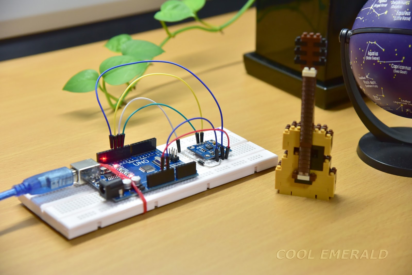
Figure. My experiment setup.
NXP ရဲ့ LPC54102 dual core ARM microcontroller ကို သုံးပြီး accelerometer တွေနဲ့ ၊ gyroscope ကိုဖတ်တဲ့ Reading IMU using ARM in C on GitHub ပါ ရေးကြည့်ခဲ့ပါတယ်။

Figure. A gyroscope and 4 accelerometers on the bottom side, and a dual core ARM microcontroller on top side of an in-house built embedded circuit board (Ø < 1 in).

Figure. An embedded inertial measurement unit using LPC54102 ARM microcontroller.

Figure. Schematic for gyroscope.
ဒါကတော့ 8051 microcontroller ကို သုံးပြီး gyroscope ကိုဖတ်တဲ့ code နမူနာ လေး နဲ့ သူ့ရဲ့ schematic ပါ။

Figure. An embedded inertial measurement unit using an 8051 microcontroller.
No comments:
Post a Comment